
|
In this article Graham Baxter, G8OAD
and Steve Smith, G8LMX explain some fundamentals of quartz
crystal temperature turning points and describe how they fine
tuned their Z3801A oven oscillators. They adjusted the oven
operating temperature to closely match the inherent
temperature turning point of the quartz oscillator. Careful
measurements and patience can pay off in improved crystal
oscillator characteristics.
|
Graham was fortunate with his Z3801A. It was one of the
comparatively few units whose clock oscillator was well behaved, and
was eventually able to settle with a predicted uncertainty of around
300 ns.
However, Steve had one which seemed less
stable. The problem moved with the oscillator, so it was
determined that there was a fundamental difference between them. To
explore this without damaging his good oscillator, Graham bought a
second Z3801A which was known to be less stable. Steve had
dismantled his and examined it several times but had reached no firm
conclusions.
Since the problems seemed to be temperature related, we
wondered if the inner oven temperature was not correctly set to the
turning point of the system.
For an explanation we need to look at the graph of Figure 1
which is frequency versus temperature for an SC cut crystal. It is
in the form of a cubic with two points of inflection. The lower
temperature, or "lower turning point" is a frequency maximum. The
upper turning point is a frequency minimum. If the temperature can
be placed exactly on a turning point, then the temperature
coefficient of frequency will be zero. This means that for very
small perturbations of temperature, there will be no change in
frequency. This is an ideal that cannot be completely realized,
since the crystal is also sensitive to temperature gradients, and it
also exhibits some hysteresis. However, these effects are minimized
in the case of the SC cut crystal compared to the AT
cut.
Figure
1
The upper turning point is most commonly used for an AT cut
crystal, where it can be typically arranged to occur at 65 - 85
degrees. However, the upper turning point for an SC cut crystal
often is too hot for reliable use in an oven, so the lower turning
point is usually chosen. To find the correct temperature, one simply
has to adjust it for a frequency maximum. It sounds easy, but keep
in mind that we are aiming for a precision of a few
milli-degrees.
|
Z3801A inner oven
temperature bridge
|
The temperature controller of the 10811 has a bridge, which
comprises three precision resistors and a thermistor that changes
resistance according to temperature. The thermistor is embedded
within the inner oven, but the component wire leads are accessible.
There is a 'select on test' resistor, whose value is chosen in
accordance with the temperature that is marked on the crystal.
However, this assumes that the crystal was correctly marked when
new, that the turning temperature has not changed, and that the
turning temperature of the assembled oscillator is identical to that
of the crystal alone. We decided to ignore the markings on the
crystals and start from scratch.
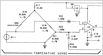 Figure 2
Z3801A
inner oven temperature bridge
The first step must be to accurately measure the bridge
resistors. If any resistors have drifted from their marked values
they must be replaced, otherwise they will continue to drift.
Fortunately, our resistors seemed beyond reproach.
Our procedure was to bring test leads to the outside of the
double oven so that the bridge temperature could be varied at will.
This had to be done with some care. We decided to use a length of
the very lightweight twin screened cable of the kind used for tape
head connections.
The 'lower' end of the thermistor, and the lower resistor on
the opposing side of the bridge were disconnected and carefully
connected to the two inner wires of the screened cable. The braid
was connected to the original common point of the thermistor and the
resistor as shown in Figure 3.
A
note was made regarding which color conductor was connected to the
thermistor. A small hole was drilled in the oven casing and the lead
was passed through. The inner oven was then reassembled.
The
reasons for doing this were:
|
We
did not know in advance which way the temperature needed to be
moved.
By
introducing identical wiring into both halves of the bridge,
the effects of the cable resistance, temperature coefficient,
and any thermal e.m.f. would tend to cancel.
The
braid would be connected to the negative supply, which is at
RF ground. |
A
note was made regarding which color conductor was connected to the
thermistor. A small hole was drilled in the oven casing and the lead
was passed through. The inner oven was then reassembled.
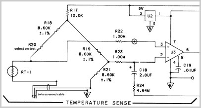
Figure 3
Z3801A oven temperature bridge with external
wiring
During manufacture the connecting leads to the inner oven are
passed twice around the inner oven. They are then routed through the
outer oven and twice around that as well. This was done to minimize
the effect of thermal shocks traveling down the copper. We
considered it was important to replicate this technique with the
routing of the screened lead, so it was dressed to follow a similar
path.
The outer oven was reassembled so we now had clock assemblies
with just an extra twin screened wire. If the two inner wires are
connected to the braid, the system will work as before. For the next
stage you need a resistor substitution box, or a precision low-value
multi-turn pot and a selection of high stability resistors.
Arbitrarily choose an inner core and connect it to the resistor
substitution system. Connect the braid and the unused inner wire to
the other end of the resistor system. Start with the resistor set to
zero and allow the system to stabilize for a few days.
The task of finding the turning point is made much easier if
you have a second frequency standard with good short-term stability.
It is possible without one, but it is a very tedious task.
The procedure we followed was:
Put
the Z3801A into holdover and let it recover from the initial
disturbance for about 20 minutes.
Compare the frequency of the Z3801A with that of
your secondary standard. One way is to externally trigger your
oscilloscope from the standard oscillator and watch the Z3801A
signal drift. We used a phase meter and a data logging system
to plot graphs.
Introduce some resistance of about 100 ohms. You
might see a small transient disturbance, but wait two minutes
and note the effect on the frequency. If the frequency has
fallen, add a further increment to make absolutely sure. If it
continues to fall, then you are moving away from the turning
point. This means that you chose to start with the wrong wire!
Correct it and allow it to stabilize again.
Continue moving the temperature until the
frequency reaches a maximum and starts to
fall. |
Make plenty of notes, since one change every ten minutes is
adequate and you may get distracted from your adjustment procedure.
When you have a rough idea of the amount of resistance to be added,
fit a high quality fixed resistor of a value a little less than the
needed value, and then explore again in smaller increments. The
reason for fitting the fixed resistor in series with the variable
one is to avoid having the temperature coefficient of the resistor
box involved in the measurements.
We
found that Graham's Z3801A needed to go cooler by the equivalent of an extra 1750 ohms
in the resistive side of the bridge. On the other hand, Steve's
oscillator needed to go hotter by 1880
ohms in series with the thermistor. In both cases they were in error
by several degrees. It is well worth spending a few weeks tuning the
temperature, ultimately in one-ohm steps. The Z3801A can still be in
normal use apart from the short spells of holdover.
Explore in both directions. Hopefully you will find a value
where an ohm either way makes no difference. In the absence of a
second standard it is just about possible to perform the adjustments
while observing the TI during holdover. However, there is limited
resolution available, and the GPS signal is not really stable enough
in the short term.
Once you are absolutely convinced that you have found a
frequency maximum, you will need to dismantle the oscillator once
more and carefully fit a fixed resistor of the exact measured value
into the appropriate position at the lower end of the bridge. There
is no need to allow for the resistance of the cable since it
affected both sides of the bridge equally. Seal the hole with solder
and reassemble. The performance should further improve once the
selected resistor is in the oven.
|
(a) Be wary of making too large a change of temperature
in one step. The Z3801A monitors the oven health signal, and
if it sees the heater turn full on it flags this as an error
and resets.
(b) Keep your cell phone away from the
resistor substitution wiring.
(c) We paid a lot of
attention to C18. We measured the leakage current vs
temperature for a selection of brand new film capacitors. We
never found one to outperform the original C18.
|
|
OK, I need an 1880 ohm resistor.
Now what?
Rather than try to use a high tolerance precision
resistor of .1 per cent or better, you are likely to achieve
results closer to your target value by simply selecting a
resistor from a low tolerance batch. Assuming you have a
reasonable digital ohmmeter, finding your specific resistor
should not be too difficult.
Searching from a group of five per cent resistors is
probably easier than limiting your search to a batch of one
per cent resistors because the 5 per cent batch will have a
tendency to have distributed values. Also, if you need to add
a total of 1880 ohms to the circuit, using a resistor within
plus or minus ten ohms is going to make a very big improvement
to the circuit.
A little patience sorting through some low cost high
stability (carbon or metal film) resistors should yield a
value nearly at your target, and at a cost much less than
using a high tolerance precision value
resistor.
Steve Smith reported that he and Graham were able to
find their exact values amongst their 5% high stability
resistors at a cost of only a few pennies each. With care, there is
room to allow the use of two
resistors. |
|
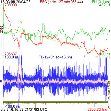
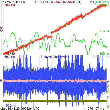
Before and after GPSCon
performance charts illustrate the benefits of fine tuning the
oven temperature to closely match the turning point of the
quartz oscillator. Obvious improvements in EFC stability (red
trace) and lower overall predicted uncertainty values (green
trace) are shown. On both charts the TI (blue trace) is the
same scale. The reduction in 'noise' is significant when both
charts are compared.
The apparent high aging rate of the "after" plot is due
to the receiver being inactive for over four weeks because of
an unrelated fault and not as a consequence of the temperature
tweak. This is why the early aging rate is so steep in the
"after" plot. |
Oscillator performance before
adjustment
Oscillator performance after
adjustment
|
How the measurements were
made |
|
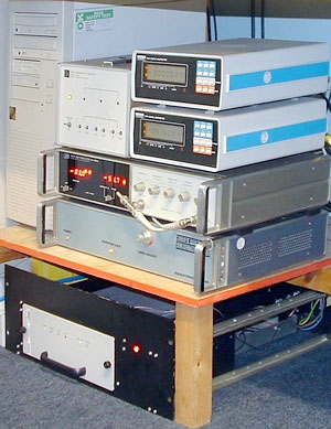
The phase measurement of the rubidium to GPS is done
with a HP 3575A phase meter with its recorder output connected
to a Solartron 7150 GP-IB multimeter. This in turn is logged
by Graham's customized Viewer program which he has modified to
read from an IEEE-488 card in the PC. This gives a resolution
of less than 10 pico seconds.
The temperature plots are done with Steve's custom
designed serial interface PIC board, also logged by Graham's
Viewer program, with 10 bits of resolution. Some of the
equipment below is home constructed. Notice Steve's use of a
recycled HP equipment cabinet (bottom in the photograph) for
his rubidium oscillator. |
|
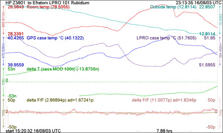
The logger is plotting the air temperature of the part
of the room where the frequency standards are located. It is
also plotting the output of a phase meter which is scaled to
display nanoseconds of time difference between the 10 MHz
outputs. The time trace is also differentiated, filtered and
scaled to produce an instantaneous fractional frequency error.
|
Copyright © 2003-2006 by Graham Baxter, G8OAD
and Steve Smith, G8LMX